A CPU needs information to process if its name is to be believed. There's a slight issue, however: the processor itself has no capacity to store information; its only capabilities are to take in fixed-length sequences of bits, called words, perform some basic mathematical operation on them, and send the result on its way to someplace outside of itself. Because of this, the CPU needs a place to remember the stuff it still needs to work on as well as a place to remember the stuff it already has worked on-- it needs a memory.
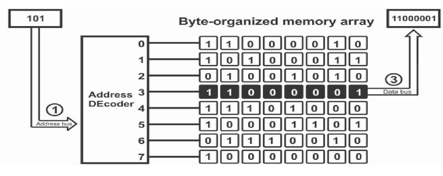
In this project, we utilized three layers of memory, the first and lowest of which being RAM. RAM is architecturally structured in grids with rows and columns, with rows typically containing some handful (4-8) words within them. This division of rows into handfuls of words has obvious benefits: instead of picking out precisely what bits from a given row we want to extract-- a very expensive operation in hardware-- we can just specify a small integral number to select a particular word in a particular row.
Programmatically, we implemented RAM as a two dimensional array. This not only mirrors the
hardware organization, but also saves us some headache. Since we work with a small number of
words per row, we can use the second index of the array to choose which word of a given row we want.
Thus, our 2D array is
RAM[RowNum][WordInRow].
This is much more manageable then thinking of all the possible shifts that would be
necessary to extract one particular bit!
Our next layer of memory on top of that was a cache. A cache is like a memory cheat-sheet: it
records a small list of places in memory we've recently been, as well as the values stored there.
Despite their simple purpose, caches become one of the most important structures in optimizing performance.
Caches are placed physically closer to the CPU than RAM and thus take less time to talk to. If we go to
retrieve some data from an address and it happens to be in the cache, then we cut our trip short and
save some time. By intelligently picking what and when to write stuff down, you can end up taking
many a shortcut on trips out to memory.
Our CPU was supported by a write-through, no allocate cache. This means that when we go to put
processed data back into memory, we copy down the new value to both the cache and RAM; the value
is "written through" the cache down to the lowest level of memory.
Importantly, however, we only copy the new value to the cache if it is currently there.
In the case that the new value does not exist in the cache, then we completely ignore the cache
and only record the change in RAM.
There are a myriad of other policies caches can implement besides write-through, no allocate,
as well as a large conversation of how you actually record down the places you've been, but I
am glossing over those details for the purposes of
this post.
The final level of memory we implemented was a set of 16 registers. Registers are super close
to the CPU and as such have almost zero transit time when delivering words to the processor.
In comparison to RAM and cache, registers aren't generally thought of as storage. They're more
akin to the scratchpad the CPU works on when processing data. Registers are responsible for
holding the stuff the CPU is immediately about to process, as well as hold the result
of the CPU's processing immediately after computation. As such, registers get used the
most out of any other memory component and generally the more of these you have on hand the better.
Some registers are reserved for special kinds of functions, with the main one of note being the
instruction pointer, or IP. The job of the IP is to track what piece of data the CPU
is currently looking at, so we know where to look for the next piece of data. If we think
of data living in memory sequentially, with Data 1 at RAM[0][0] and Data 2 at
RAM[0][1], then after we process Data 1, we increment the IP one step so we know to
go get Data 2 at the next index. Registers are also the part of memory that is most affected by
how big a word is. Since registers are responsible for feeding words into a CPU,
they are the same size as a word.
In our project, we had a word size of 32 bits. Because of this, we were able to codify
registers as an array that stored 32 bits each. Each index would correspond to one specific
register.
When simulating the CPU's interactions with memory, we wanted to make sure this idea of on-chip distance carried over. To do this, we simply waited an increasing amount of time as we asked to retrieve memory from further and further components. Registers spent no time waiting, whereas cache and RAM would spend 1 and 10 cycles respectively stalling.
Now that we've established where we store things, it's time to think about what we'll be storing. We introduced the idea of words before, but what do words really say? They tell the CPU what to do through information called instructions. Instructions are special sequences of bits that a CPU is designed to recognize. For example, if I feed a specific CPU the sequence of bits 01001 001 010, it will interpret that as an instruction to add the values 1 and 2. CPU designers publish instruction set architectures, or ISAs, to describe the format and structure of sequences specific CPUs can interpret. Each ISA has its own structure describing the size instructions could be, as well as how different parts of a bit sequence translate to adding or comparing two values.
Our simulated CPU understood the MIPS-1 ISA. MIPS-1 has a fixed 32-bit word size, meaning that every instruction had to fit within 32 bits; anything larger than that would be malformed and the CPU would be unable to process it. Let's take a look at an example of a MIPS-1 instruction to see how this works.

We can see here how the 32 bits of one instruction are split up. The first 6 bits, or "op" field,
correspond what operation is performed. This would mean that something like 000001 corresponds to
addition, 000010 corresponds to subtraction, etc. The next three fields describe what registers are involved
in the operation to perform. The first two are the registers to use as operands for the operation, and the
third is the register to store the result into. The last two fields encode operation specific information,
such as the amount to shift for logical operations, so we can gloss over those. To put this idea into practice,
here is an instruction that subtracts registers 1 and 4 and stores it in register 3 (R3 = R1 - R4):
000010 00001 00100 00011 00000 000000
Now, hand writing instructions in this format is a punishment fit for Guantanamo, so we quickly
developed a tool that can help automate this process. It is the job of an assembler to take
assembly, a kind of ultra-simple programming language, and turn it into these
one word instructions.
So, instead of having to write the above instruction in binary format, we can write the much more
understandable sub r1 r4 r3, feed that to the assembler, and it emits the above binary
value. Don't believe me?
Try it out yourself and prove me wrong!
With the 'what' and the 'where' taken care of, we can now think about how these instructions are processed on the processor. There are a couple different disciplines on how to divide this up, with the simplest consisting of three stages, where the processor fetches an instruction, decodes it, and executes the operation specified. There are many ways to refine and modularize these three stages; in our project, for instance, we made use of a five stage processing pattern. These five stages are: first fetching an instruction to process; decoding it; executing the operation said instruction encoded; interacting with memory if needed; and finally writing back the results of the operation to places in memory. Let's take a closer look at these.
The fetch stage of processing is
self-explanatory.
In this part of processing, a new instruction is retrieved from somewhere in memory according to the IP.
While fetching largely happens in strictly linear order, there are occasions where we would need to fetch
from many disparate addresses for every instruction in a sequence. Consider a series of function calls or
many control flow structures like if-else blocks or loops: instructions may come from code
segments that are many addresses above or below the one we are currently executing.
The decode stage is responsible for interpreting what a given instruction says to do. Earlier in this blog post, we encoded a subtraction instruction into a 32-bit number. The decode stage does the opposite of this: it slices an instruction up into its constituent parameters, and creates pathways to the respective registers to be used. It also sends signals to other necessary bits of hardware around the CPU to perform whatever operation the instruction dictates, such as an Algorithmic Logic Unit for mathematical operations, or another chip dedicated to cryptographic functions.
The execute stage executes the current instruction. Nothing much else to it, really. From a hardware perspective this stage deserves more interest, as the CPU may talk to peripherals such as the aforementioned cryptographic components, but besides that, it the CPU just does what it was instructed to do.
The memory stage is where any I/O instruction does its thing. Instructions such as loading or storing from an address would wait until this stage to actually go about doing those memory operations. This also would be the stage where a cache's contents would be updated For instructions that don't access memory, this stage is ignored.
The writeback stage is where the result of the CPU's current computation is published. This could consist of storing the result of an arithmetic or logical instruction in a register, for example, or changing the IP based on the result of a jump instruction.
That's a surprising amount of steps to get through, isn't it? Even though every step individually is fairly intuitive to understand, a CPU gains a great deal of emergent complexity when we consider all these steps simultaneously. To further complicate things, we should also consider the fact that a reasonable program could easily have a thousand instructions, and that a computer runs at least several hundred of such programs concurrently, and all of this needs to be fast enough that an end user like you or me doesn't feel any latency when we move our mouse or type a key! The workload placed on a CPU is not one to take lightly.
There's one large inefficiency about the style of processing that we explained in the previous section: we can only do one thing at a time. When one instruction enters the CPU, it must go through all five of the above stages of processing before we can begin to fetch the next instruction. This isn't effective for performance: to make a computer fast, we want to maximize the amount of instructions we can send through the CPU in very short time spans, a quantity known as its throughput. In order to improve throughput, we need to increase the number of instructions we are processing at once.
Fortunately, the structure of the Fetch-Decode-Execute-Memory-Writeback loop lends itself well to modularization. We can notice that each stage of the loop is relatively independent. Once we fetch an instruction and pass it off to be decoded, there's no reason why we can't begin fetching another. Similarly, if one instruction skips the memory stage, and its immediate successor makes use of memory, why not have that successor do I/O while the first instruction writes back its contents to registers? If we generalize this idea, then we would have each stage of the F-D-E-M-W loop operate in near complete independence of each other, with each stage handling a unique instruction. With such a construction, we can now have five separate instructions running at a time-- five times the throughput we had previous! This kind of construction is called a pipeline, because instructions flow from one stage to another, much like water through an actual pipe. Every CPU created today and onward uses pipelines instead of the monolithic style of processing; the performance boosts they provide have proven indispensable in making computers run fast.
Unfortunately, having so many independent instructions running at once does not come without its issues. Since every stage of the pipeline is working on something different, we now need to coordinate communication between the stages. To do so, we'll put every stage on a timer, called a clock. The clock is a pulse of electricity that occurs in fixed quantities of time, called clock cycles. You can think of a clock cycle much like the movement of the second hand on an analog clock. Every second, the second hand moves immediately to its next position in discrete increments; there's no "in-between" time, just one second and the next. The clock acts as a timer for stages to do their work, with the actual work occuring between cycles. For example, say we are currently at clock cycle 0. When we receive the notice that we have entered clock cycle 1, we begin fetching a new instruction. When we arrive at clock cycle 2, we have finished fetching and deliver that instruction to the decode stage. Thus, the work needed to fetch an instruction is done between clock cycles 1 and 2, with the handoff happening at clock cycle 2. Ideally, decoding this instruction would also take one cycle, between cycles 2 and 3, with the following stages following suit and only taking one clock cycle each.
In practice, we don't get to deal with ideal cases. Pipeline stages can take much longer than one measly
cycle-- memory is an especially common offender-- and because of this, things don't flow easily from one stage
to the next. The execute stage might not be able to pass forward its result, because the memory stage is
stuck doing an outgoing memory access. Because of this, the decode stage cannot pass along a decoded
instruction to execute, and suddenly our entire pipeline is all gummed up! To account for this, every stage
of the pipeline needs the ability to wait, or stall, until it can pass forward the result of its
processing.
Jumping and branching also presents some noticeable issues. Normally, we'd want to fetch instructions in
linear order: instruction 5 would be fetched after instruction 4, which was fetched after instruction 3, etc.
In the case where we jump, though, this isn't the case; we could jump to any arbitrary address. It takes
a while for a jump to be processed, since that only occurs in the writeback stage when we publish it to
the IP. We now have four instructions in the previous four stages which are out of date! This motivates
the need to have a way to empty the pipeline and throw away everything we're working on, lest we
start operating with the wrong instructions. Imagine if the first few lines of an if-block
always executed, even when you took the else-block.
These complications made the pipeline easily the most challenging part of the project to implement. In order
to keep ourselves straight and the instructions flowing, we conceptualized a "back-and-forth" flow throughout
the pipeline. Every pipeline stage had a struct associated with it that held pertinent information: the fetch
stage's struct had an address to fetch at and a place to store the fetched instruction, the decode struct
had fields to account for all possible operations and operands, and so on. At the top of every cycle, each stage
in reverse order would take the information in its struct and do its thing with it. This means that
the writeback stage would update registers as needed, and then set a boolean saying it is ready for new information.
Then the memory stage would do its thing, then execute, all the way back up the pipeline. This is the "backwards"
flow of execution.
We would then follow the pipeline forward: the fetch stage would look at the decode struct and
check its boolean to see if it is currently available to receive information; if so, it would take its result
and populate the decode struct accordingly. The decode struct would then do the same with execute, flowing
forward through the pipeline. Once both back and forward motion is complete, we then increment the clock
cycle counter and start the process all over again. It was only more intensive than this paragraph made it
out to be, don't worry.
Even with all the content I have covered thus far, there is still more yet to talk about. The scope of our project encapsulated everything up until the five stage pipeline we just finished discussing, and even that was quite a mighty task. If we go in to consider concepts like speculation, branch prediction, vectorization, out-of-order execution and further, then this blog post may seem even more insurmountable then it does at present. I would love to tackle these ideas in future work, as they are now the bare necessities for modern processors. We had our hands plenty full getting all of this up and running, though, so I anticipate a long while before I jump all the way down to the metal again.
Don't let my exploration of further ideas come off in a "grass is always greener" sense, though! We built a CPU with plenty of sophistication to it, and we can do plenty with it in its current state. We can run benchmark tests to stress different aspects of the instruction pathway: perhaps a workload we construct exercises the cache a lot, and measures how much performance is affected because of it. Or, maybe we construct a simple program consisting of tons of jumps, causing the pipeline to be constantly emptied out as we get code from many different addresses. Maybe we just want to play around with the assembler and try to write many different programs in this reduced programming language; that's also just swell!
I hope you found this entertaining, insightful and motivational, all in equal parts. If that's asking too much, then I'll settle for just the first.